TP-LINK AC750 UART pins
Having root is fun, talking to the UART is better.
Opening up the device was quite a hassle, there are two screws and the rest is fastened using plastic clips. I had to break a couple of clips when I opened the device. I honestly don’t see how you can open the device without breaking these clips.
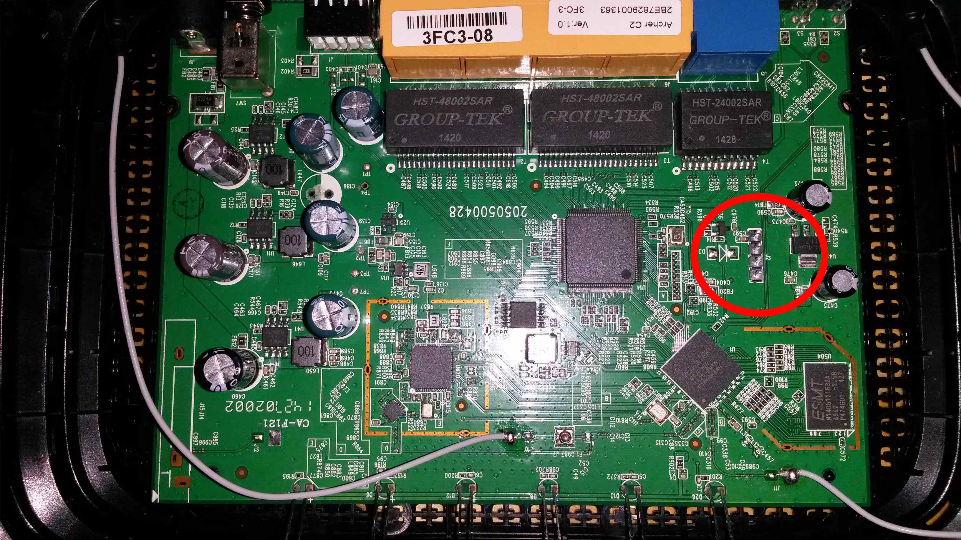
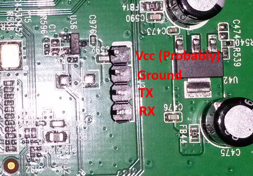
There are 4 solder pointers on the board with a label “J2”, I guessed this was where you can connect the UART. And it turns out I was right. I soldered a 4-pin header on the board to make it easier to connect a serial cable.
I first tried this with an Adafruit 4 Pin Cable (PL2303). But sadly, I blew it up connecting it to the 3.3v pin (or, at least, I think that is wat caused it.)
After which I tried, what I believe originally was a Nokia phone connector cable which can be (ab)used as a 3.3v serial cable. And yay! It worked.
This is the pin-out on the board. Pin 1 is the pin with the white dash above it.


J2
| Pin | Function |
|---|---|
| 1 | Probably 3.3v. |
| 2 | Ground (Connected to ground) |
| 3 | TX (Connected to RX) |
| 4 | RX (Connected to TX) |
The Nokia phone connector
| Cable | Function |
|---|---|
| Black | Ground |
| White | RX |
| Blue | TX |
The baudrate is: 115200
You can find a dump of the successful UART connection here. Note that I entered the password wrong twice.
